您现在的位置是:主页 > 网络技术 >
干货!思科交换机配置命令大全,附配置案例
正文
一、思科交换机基本配置命令
1:进入特权模式 enable
switch> enable
switch#
2:进入全局配置模式 configure terminal
switch> enable
switch#configure terminal
switch(conf)#
3:交换机命名 hostname aptech2950 以 aptech2950 为例
switch> enable
switch#configure terminal
switch(conf)#hostname aptch-2950
aptech2950(conf)#
4:配置使能口令 enable password cisco 以 cisco 为例
switch> enable
switch#configure terminal
switch(conf)#hostname aptch2950
aptech2950(conf)# enable password cisco
5:配置使能密码 enable secret ciscolab 以 cicsolab 为例
switch> enable
switch#configure terminal
switch(conf)#hostname aptch2950
aptech2950(conf)# enable secret ciscolab
6:创建多个vlan
1、创建多个VLAN
Switch>enable (进入特权模式)
Switch#vlan data (进入vlan配置模式)
Switch(vlan)#vlan 10 name IT (划分vlan10,名称为IT)
Switch(vlan)#vlan 20 name HR (划分vlan20,名称为HR)
Switch(vlan)#vlan 30 name FIN (划分vlan30,名称为FIN)
Switch(vlan)#vlan 40 name LOG (划分vlan40,名称为LOG)
Switch(vlan)#exit
7:设置 vlan 1
switch> enable
switch#configure terminal
switch(conf)#hostname aptch2950
aptech2950(conf)# interface vlan 1
aptech2950(conf-if)#ip address 192.168.1.1 255.255.255.0 配置交换机端口 ip 和子网掩码
aptech2950(conf-if)#no shut 是配置处于运行中
aptech2950(conf-if)#exit
aptech2950(conf)#ip default-gateway 192.168.254 设置网关地址
8:进入交换机某一端口 interface fastehernet 0/17 以 17 端口为例
switch> enable
switch#configure terminal
switch(conf)#hostname aptch2950
aptech2950(conf)# interface fastehernet 0/17
aptech2950(conf-if)#
9:查看命令 show
switch> enable
switch# show version 察看系统中的所有版本信息
show interface vlan 1 查看交换机有关 ip 协议的配置信息
show running-configure 查看交换机当前起作用的配置信息
show interface fastethernet 0/1 察看交换机 1 接口具体配置和统计信息
show mac-address-table 查看 mac 地址表
show mac-address-table aging-time 查看 mac 地址表自动老化时间
10:交换机恢复出厂默认恢复命令
switch> enable
switch# erase startup-configure
switch# reload
11:双工模式设置
switch> enable
switch#configure terminal
switch2950(conf)#hostname aptch-2950
aptech2950(conf)# interface fastehernet 0/17 以 17 端口为例
aptech2950(conf-if)#duplex full/half/auto 有 full , half, auto 三个可选
项
11:cdp 相关命令
switch> enable
switch# show cdp 查看设备的 cdp 全局配置信息
show cdp interface fastethernet 0/17 查看 17 端口的 cdp 配置信息
show cdp traffic 查看有关 cdp 包的统计信息
show cdp nerghbors 列出与设备相连的 cisco 设备
12:交换机 telnet 远程登录设置:
switch>en
switch#configure terminal
switch(conf)#hostname aptech-2950
aptech2950(conf)#enable password cisco 以 cisco 为特权模式密码
aptech2950(conf)#interface fastethernet 0/1 以 17 端口为 telnet 远程登录端口
aptech2950(conf-if)#ip address 192.168.1.1 255.255.255.0
aptech2950(conf-if)#no shut
aptech2950(conf-if)#exit
aptech2950(conf)line vty 0 4 设置 0-4 个用户可以 telnet 远程登陆
aptech2950(conf-line)#login
aptech2950(conf-line)#password edge 以 edge 为远程登录的用户密码
主机设置:
ip 192.168.1.2 主机的 ip 必须和交换机端口的地址在同一网络
段
netmask 255.255.255.0
gate-way 192.168.1.1 网关地址是交换机端口地址
运行:
telnet 192.168.1.1
进入 telnet 远程登录界面
password : edge
aptech2950>en
password: cisco
aptech#
二、利用三层交换机,实现不同vlan间互相通信
上面我们了解了思科交换机的基本配置命令,下面我们来看下配置案例。
案例如下:
pc1与pc2由于阻绝在了两个不同的交换机里,且在不同的vlan中,是无法通信的,那怎么办呢?
S3550-24(三层交换机)1台、S2126交换机1台、pc1在vlan10里,pc2在vlan20里,如下图所示。
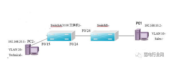
VLAN间通信实验拓扑结构图
配置如下:
1、在交换机SwitchA上创建VLAN 20,并将F0/15口划分到VLAN 20中。
SwitchA>enable
SwitchA#configure terminal
SwitchA(config)#vlan20 //创建VLAN 20
SwitchA(config-vlan)#name vlan20 //将VLAN 20 命名为vlan20
SwitchA(config)#interface f0/15 //进入F0/15接口配置模式
SwitchA(config-if)#switchport access vlan 20 //将F0/15端口划入VLAN 20
SwitchA #showvlan id 20 //验证已创建了VLAN 20并已将F0/15端口划入VLAN 20中。
2、在交换机SwitchA上与SwitchB相连的端口(此处为F0/24端口)定义为tag vlan 模式。
SwitchA>enable
SwitchA#configure terminal
SwitchA (config)#interface f0/24 //进入接口配置模式
SwitchA (config-if)#switchport mode trunk //将F0/24口设置为tag vlan模式
SwitchA (config)#show interfaces f0/24 switch //验证F0/24口已被设置为tag vlan模式
3、在交换机SwitchB上创建VLAN 10,并将F0/5端口划入VLAN 10中。
SwitchA>enable
SwitchA#configure terminal
SwitchB(config)#vlan 10 //创建VLAN 10
SwitchB (config-vlan)#name vlan10 //将VLAN 10 命名为vlan
SwitchB (config)#interface f0/5 //进入F0/5接口配置模式
SwitchB (config-if)#switchport access vlan10 !将F0/5端口划入VLAN 10
SwitchB #show vlan id 10 //验证已创建了VLAN 10并已将F0/5端口划入VLAN 10中
4、在交换机SwitchB上与SwitchA相连的端口(此处为F0/24端口)定义为tag vlan 模式。
SwitchA>enable
SwitchA#configure terminal
SwitchB (config)#interface f0/24 //进入接口配置模式
SwitchB (config-if)#switchport mode trunk //将F0/24口设置为tag vlan模式
SwitchB (config)#show interfaces f0/24 switch //验证F0/24口已被设置为tag vlan模式。
5、设置三层交换机VLAN 间通讯,开启三层交换机的路由功能
SwitchA>enable
SwitchA#configure terminal
SwitchA(config)#ip routing //开启三层交换机的路由功能
SwitchA(config) #interface vlan 10 //创建虚拟接口vlan10
SwitchA(config-if) #ip address 192.168.10.254 255.255.255.0 //配置vlan10的虚拟接口ip地址
SwitchA(config) #interface vlan 20 //创建虚拟接口vlan20
配置vlan20的虚拟接口ip地址
SwitchA(config-if) #ip address 192.168.20.254 255.255.255.0 //配置vlan20的虚拟接口ip地址
6、配置默认网关
将PC1的默认网关设置为192.168.10.254,将PC2的默认网关设置为192.168.20.254。
如此,pc1与pc2便可以相互通。
随机图文

齐齐哈尔医学院智慧教室建设项目(二次)结果公告
齐齐哈尔医学院智慧教室建设项目(二次)结果公告 2022年01月05日 14:06 来源:中国政府采购网 【打印】 【显示公告概要】 一、项目编号:GXQ2021-404.1B1 二、项目名称:智慧教室建设项目(二次)
品至干货!弱电工程项目绩效考核评价与薪酬分配管理办法(试行)
内容加密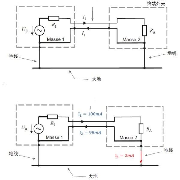
从接地系统的一个小问题入手,掌握最全的设备接地知识!
提到接地系统,可以说一直是大部分弱电从业者的难点。一方面是接地系统更多用于强电中,另一方面在弱电实际工程中很多人接触接地系统也不多。但是对于接地的原理我们应该是要掌握的。有人问:为什么回路电流走零线不走地线,而漏电流走地线不走零线,零线地线原理是什么? 如图所示, 一直搞不清楚地线和零线的原理, 地线的两端分别是什么,保护中性线的两端是什么。漏电流为什么走的地线而回线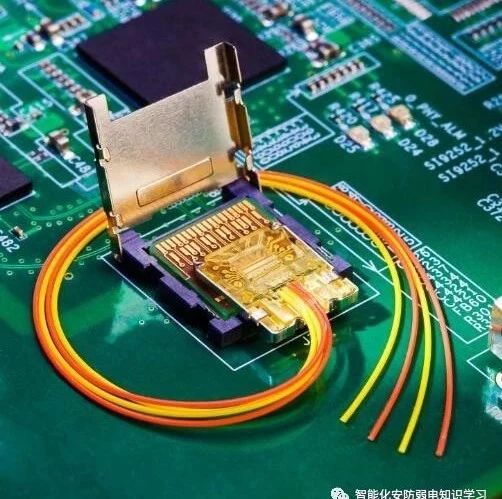
光纤弯折会影响网速吗?光纤受损,如何处理?
有很多朋友问品至,如果光纤可以弯曲吗?最底可以弯曲多少没有影响?在了解这个问题的同时,我们需要先了解下光纤传输的原理。 你有没有经历过WIFI突然断掉,有没有经历过反复重启,仍觉得网速卡慢?出现这些问题的原因除了路由器本身之外,还有可能是你家的光纤线出现了问题。 光在光纤中传播主要是依据全反射原理。光线垂直光线端面射入,并与光纤轴心线重